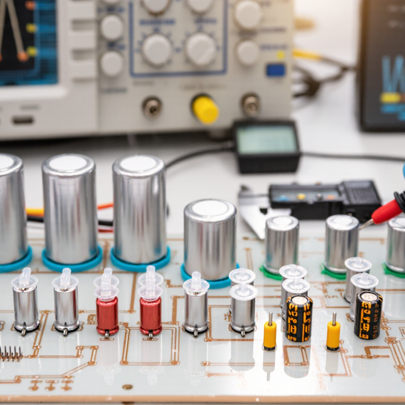
| 1 | Match the dielectric material to the application | Polypropylene (PP): very low dielectric loss, typically below 0.1% at 1 kHz.
Polyester (PET): commonly about 0.5–1.5% at 1 kHz.
PPS: commonly about 0.1–0.3% at 1 kHz. | Dielectric loss, insulation resistance, dielectric strength, physical size, and stability over temperature and frequency. | Select PP for low-loss filtering, resonant circuits, and power conversion. Use PET where compact size and general-purpose performance are more important than minimum loss. Consider PPS when high temperature stability and low loss are required. |
| 2 | Check the operating-temperature rating | Common upper temperature classes include approximately +85°C, +105°C, +125°C, and +150°C. Typical lower limits range from about −40°C to −55°C, depending on construction. | Ambient temperature, internal hot-spot temperature, ripple-current heating, and the required service life at the maximum temperature. | Do not size the capacitor only from the ambient temperature. Allow thermal margin for self-heating, especially in enclosed equipment, power supplies, motor drives, and high-ripple applications. |
| 3 | Evaluate frequency performance and loss | Film-capacitor impedance generally decreases with frequency until ESR and ESL dominate. PP normally offers very low dissipation, while PET has higher dielectric loss. Actual limits depend on winding geometry, lead length, voltage, and capacitor size. | Dissipation factor, ESR, equivalent series inductance, impedance-versus-frequency curves, and allowable RMS current at the intended frequency. | For switching frequencies, resonant networks, and EMI filters, review manufacturer frequency curves rather than relying only on the nominal capacitance and voltage rating. |
| 4 | Confirm voltage and transient capability | Metallized film capacitors are available for low-voltage signal circuits through high-voltage power applications. DC voltage, AC voltage, pulse voltage, and repetitive peak voltage are separate specifications. | Maximum continuous voltage, peak voltage, polarity, dv/dt, pulse energy, and the effect of temperature on voltage capability. | Apply suitable voltage derating for transients and long service life. Never substitute an AC RMS rating for a DC or repetitive-peak requirement without checking the applicable specification. |
| 5 | Consider self-healing behavior and capacitance stability | Metallized electrodes can clear a small localized dielectric fault by vaporizing metal around the defect. This improves fault tolerance but may cause a small, cumulative reduction in capacitance after repeated clearing events. | Capacitance tolerance, long-term capacitance drift, self-healing conditions, insulation resistance, and permissible fault-clearing energy. | Use self-healing metallized film when compact construction and improved tolerance to small dielectric defects are valuable. For severe repetitive pulses, verify the specified pulse-life and self-healing limits. |
| 6 | Check humidity, insulation, and environmental suitability | Moisture can reduce insulation resistance and increase dielectric loss. Sealed or resin-filled constructions generally provide better environmental protection than unsealed constructions. | Climatic category, humidity testing, insulation resistance, encapsulation, corrosion resistance, vibration, and altitude requirements. | For outdoor, automotive, industrial, or high-humidity equipment, choose a construction with a documented climatic rating and adequate sealing. Keep lead and terminal spacing suitable for the working voltage and pollution level. |
| 7 | Verify ripple current, mechanical fit, and compliance | Ripple-current capability is limited by ESR-related heating and varies with frequency and temperature. Package dimensions, terminal spacing, flammability classification, and safety approvals also vary by design. | RMS ripple current, allowable temperature rise, case size, mounting method, creepage and clearance, flammability, and applicable safety standards. | Compare the complete electrical and mechanical specification with the actual circuit waveform. Select a higher ripple-current or temperature class when calculated hot-spot temperature is close to the limit. |