


How to Choose a Temperature Control Valve in 2026?
Choosing a Temperature Control Valve in 2026 is not a simple catalog exercise. It is a process decision with measurable consequences. The wrong valve can create unstable temperatures, wasted energy, noisy operation, and premature maintenance. A well-matched valve responds smoothly, even when pressure, flow, or load conditions change.
Control-valve specialist Béla G. Lipták has described the control valve as “the final control element in a process control loop.” That statement remains highly relevant. The valve receives the controller’s command, then physically changes the process. Its trim, actuator, body material, sizing, and control range must fit the application. Steam heating, hot-water circulation, thermal-oil systems, and chilled-water duties require different choices. Field experience also matters. A valve that performs well during commissioning may behave poorly at low demand.
This guide examines the practical selection points for a modern Temperature Control Valve. It considers media temperature, operating pressure, flow coefficient, leakage class, response speed, actuator type, connection standards, and maintenance access. Smart positioners and diagnostic data can improve visibility, but technology cannot correct poor sizing. That mistake is common. Sometimes, engineers focus too heavily on maximum flow and overlook minimum stable control. The result may be hunting, overshoot, or a barely open valve in daily operation.
Good selection starts with real operating data, not assumptions. Record normal, minimum, and maximum conditions. Check the consequences of failure. Specify a fail-open or fail-closed action based on process safety. Then compare suppliers, documentation, testing practices, and after-sales support. The best valve is not always the most advanced. It is the one that remains predictable, serviceable, and safe throughout its working life.
What Is a Temperature Control Valve and How Does It Work?
How to Choose a Temperature Control Valve in 2026?
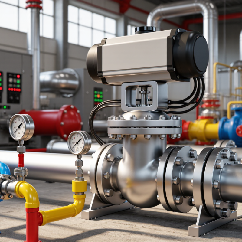
A temperature control valve regulates fluid flow to maintain a target temperature. It usually works with a sensor, controller, and actuator. The sensor measures temperature near the process or heat exchanger. The controller compares that reading with the setpoint. Then, the actuator adjusts the valve position. More heating fluid may enter. Less cooling fluid may pass.
In practical commissioning, valve hunting often appears after installation. The valve opens and closes repeatedly. This can result from oversized capacity, slow sensors, or incorrect tuning. It is not magic. A properly selected valve should match flow rate, pressure drop, fluid temperature, and response speed. Fail-open or fail-closed action also matters during power loss. Steam, water, glycol, and corrosive fluids require different body and trim materials.
Energy efficiency makes this choice increasingly important. The International Energy Agency reports that buildings consume about 30% of global final energy. Its Buildings report also attributes roughly 26% of energy-related emissions to building operations. In industrial systems, tighter temperature control can reduce overheating, waste, and product variation. The U.S. Department of Energy recommends evaluating HVAC control performance through measurement, commissioning, and continuous verification. That guidance is useful, but not flawless for every process. Operators should check real operating data rather than relying only on catalog ratings. A valve that looks efficient on paper may perform poorly with unstable pressure or a poorly placed sensor.
How to Choose a Temperature Control Valve in 2026? – What Is a Temperature Control Valve and How Does It Work?
| Selection Dimension | Available Option / Typical Data | How It Works | Recommended Use |
|---|---|---|---|
| Definition | Automatic flow-control device used to maintain a target process temperature. | It changes the flow of heating or cooling media in response to measured temperature. | Heating systems, cooling loops, heat exchangers, tanks, air-handling equipment, and process lines. |
| Basic operating principle | Temperature sensor + controller or actuator + valve body. | When measured temperature differs from the setpoint, the valve modulates flow to reduce the error. | Applications requiring automatic and repeatable temperature regulation. |
| Control mode | On/off, proportional, or modulating control. | On/off control fully opens or closes the valve; modulating control continuously adjusts the opening position. | Use on/off for simple temperature bands and modulating control for tighter temperature stability. |
| Valve configuration | Two-way or three-way. | A two-way valve varies flow through one passage. A three-way valve mixes two streams or diverts one stream. | Choose two-way for terminal flow control and three-way for mixing, bypass, or constant-flow arrangements. |
| Actuation method | Self-operated, electric, pneumatic, or electro-hydraulic. | Self-operated valves use process temperature directly; powered actuators receive a control signal and position the valve. | Use self-operated designs for local, independent control and powered actuators for integrated automation. |
| Control signal | Common analog signals include 0–10 V and 4–20 mA; digital fieldbus signals may also be used. | The controller converts the temperature error into a valve-position command. | Select a signal compatible with the building-management system, PLC, controller, and actuator. |
| Temperature measurement | Immersion, surface, room, duct, or return-line sensing. | The sensor measures the relevant process point and sends feedback to the controller or integrated thermostat. | Place the sensor where temperature represents the controlled process, not merely the nearby supply temperature. |
| Heating or cooling service | Hot water, steam, thermal oil, chilled water, glycol-water mixtures, or air. | The valve increases or decreases the energy-transfer medium entering the controlled equipment. | Confirm that the valve, seals, trim, and actuator are suitable for the actual medium and temperature. |
| Nominal size | Selected from required flow, connection size, and allowable pressure drop; it is not chosen from pipe size alone. | The internal port and valve capacity determine how much medium can pass at a given pressure differential. | Size from calculated load and flow rate, then verify connection compatibility. |
| Flow coefficient | Use the manufacturer’s applicable flow coefficient, such as Cv or Kv, for sizing. | A higher coefficient allows more flow at the same pressure differential. | Select a valve that provides the design flow near the middle portion of its controllable range. |
| Flow rate | Determine from heat load and temperature difference. For water: Q ≈ 4.186 × ṁ × ΔT in kW when ṁ is kg/s and ΔT is °C. | The required thermal duty determines the mass or volumetric flow that the valve must regulate. | Calculate design, minimum, and maximum flow before selecting the valve capacity. |
| Operating pressure | Check inlet pressure, outlet pressure, differential pressure, maximum allowable pressure, and shutoff pressure. | Pressure differential drives flow and also affects noise, cavitation risk, actuator force, and shutoff performance. | Use the complete pressure envelope, including start-up, shutdown, and abnormal conditions. |
| Temperature range | Specify minimum, normal, maximum, setpoint, and transient temperatures for the medium and ambient environment. | The sensing element and valve materials must remain stable throughout the full operating range. | Do not select a valve using the normal temperature alone; include foreseeable peaks and thermal cycling. |
| Valve body materials | Common choices include brass, bronze, ductile iron, carbon steel, and stainless steel. | Material selection affects corrosion resistance, pressure-temperature capability, durability, and compatibility with the medium. | Match the body and wetted parts to fluid chemistry, temperature, pressure, and applicable codes. |
| Connection type | Threaded, flanged, grooved, soldered, brazed, or welded connections. | The connection joins the valve to the piping system and must withstand the service conditions. | Choose according to pipe standards, installation space, maintenance needs, and pressure class. |
| Characteristic and rangeability | Linear, equal-percentage, or quick-opening characteristics; rangeability is commonly specified by the valve design. | The characteristic defines how flow changes as the valve stem or disc moves. | Equal-percentage is often suitable for variable-pressure-drop systems; verify the complete system response. |
| Fail position | Fail-open, fail-closed, or fail-in-place, depending on actuator and application. | On loss of power or control signal, the actuator moves or holds the valve in a defined safety position. | Choose the position that minimizes risk of overheating, freezing, pressure damage, or product loss. |
| Response speed | Fast response for low thermal mass; slower response may be preferred for large thermal systems. | Actuator speed, sensor location, controller tuning, and process thermal inertia determine response. | Avoid oversizing and excessive actuator speed, which can cause hunting or temperature oscillation. |
| Energy efficiency | Modulating control, correct sizing, low leakage, and suitable insulation improve system efficiency. | Accurate flow adjustment reduces unnecessary heating, cooling, pump work, and temperature swings. | Evaluate total operating cost rather than purchase price alone. |
| Maintenance requirements | Inspect seals, actuator operation, sensor accuracy, wiring, strainers, and valve travel at planned intervals. | Contamination, scale, corrosion, and worn seals can reduce control accuracy or cause leakage. | Provide isolation valves, access clearance, filtration where appropriate, and a commissioning procedure. |
Related Posts
-
Navigating Global Standards: The Impact of Import and Export Certifications on Best Flow Regulator Valve Supply Chains
-
How to Choose the Right Water Pressure Regulator Valve for Your Home?
-
Understanding the Functionality of Air Flow Control Valves
-
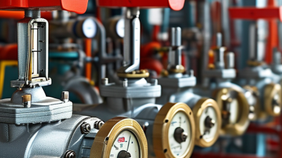
Essential Tips for Choosing Temperature Control Valves?
-
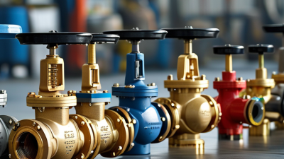
Top Steam Control Valve Options for Global Buyers in 2026?
-
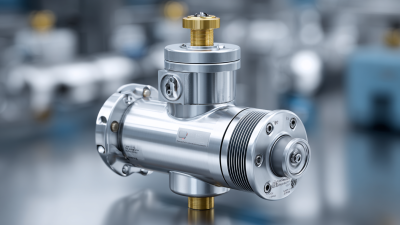
How to Effectively Choose the Right Pressure Regulator for Your Industrial Needs