2026 Best Proportional Flow Control Valve Types

The 2026 search for the best Proportional Flow Control Valve begins with one practical truth: “best” depends on the process. A valve controlling 2 L/min of coolant faces different demands from one regulating 400 L/min of hydraulic oil. Response time, pressure drop, fluid cleanliness, temperature, and actuator compatibility can change the correct choice. Small details matter. A sticky spool can distort an entire production cycle.

Industry forecasts support this growing need for accurate control. Grand View Research’s Industrial Valves Market Report identifies continued expansion through 2030, driven by automation, process efficiency, and infrastructure investment. MarketsandMarkets’ Industrial Automation Market report also projects strong growth during this period, particularly in smart manufacturing and connected control systems. These trends place proportional technology closer to everyday plant operations, not only specialist laboratories.

This guide compares major valve types, including spool, poppet, cartridge, electro-hydraulic, and pneumatic designs. It considers flow accuracy, hysteresis, repeatability, leakage, maintenance, and digital feedback. Field experience shows that a highly responsive valve may perform poorly with contaminated oil or unstable pressure. That limitation is easy to overlook. Energy consumption and total ownership cost also deserve attention, because purchase price rarely tells the complete story. No shortlist is perfect. Engineers should verify manufacturer curves, ISO test data, duty-cycle ratings, and application-specific performance before selecting equipment for 2026.

2026 Best Proportional Flow Control Valve Types

What Is a Proportional Flow Control Valve?

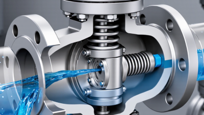
A proportional flow control valve regulates fluid flow continuously, rather than switching only between open and closed positions. An electrical command changes the valve opening, allowing operators to control actuator speed with greater precision. The input may come from a controller, sensor, or manual adjustment. In practice, a small signal can produce slow cylinder movement, while a stronger signal increases flow.

Common designs include proportional spool valves, needle-style valves, and cartridge valves. Spool valves suit directional control and moderate flow ranges. Needle designs offer simple adjustment and useful metering accuracy. Cartridge valves fit compact manifolds and high-density hydraulic systems. Some valves use pressure compensation to maintain steadier flow when system pressure changes. This feature helps, but it cannot remove every effect caused by temperature, contamination, or unstable pump output.

Tips: Match the valve’s flow range to the real operating demand, not only the maximum specification. Check signal type, response time, pressure drop, and fluid cleanliness before installation. I have seen oversized valves create poor low-speed control because tiny signal changes barely affect the opening. That choice often looks efficient on paper. It may perform badly in motion. Test the valve with the actual actuator and load whenever possible. The best selection is rarely based on one number.

2026 Best Proportional Flow Control Valve Types

What Is a Proportional Flow Control Valve?

A proportional flow control valve continuously adjusts fluid flow in response to an electrical control signal. This normalized comparison shows common inherent flow characteristics: linear trim provides an approximately proportional relationship, equal-percentage trim increases flow gradually at low openings and more rapidly at high openings, while quick-opening trim delivers a large initial flow increase. Actual performance depends on valve sizing, pressure drop, fluid properties, actuator response, and installation conditions.

How Proportional Flow Control Valves Work

2026 Best Proportional Flow Control Valve Types

How Proportional Flow Control Valves Work

A proportional flow control valve adjusts fluid flow according to an electrical input signal. The signal moves a spool, poppet, or needle inside the valve. A small signal creates a small opening. A larger signal creates a wider opening. This action gives operators smoother control than a simple on-off valve.

The controller usually sends a voltage or current signal. The valve converts that signal into mechanical movement. Flow then passes through the changing orifice. Actual flow still depends on pressure difference, fluid temperature, and viscosity. Pressure-compensated designs reduce these variations. Not every proportional valve includes this feature.

Control accuracy depends on correct sizing and calibration. An oversized valve may react sharply near its minimum setting. An undersized valve can restrict the system and generate unwanted heat. During commissioning, technicians should check inlet pressure, outlet pressure, and measured flow. A flow meter reveals problems that a command signal cannot show. Keep wiring away from strong electrical noise. Small installation details matter.

Feedback can improve performance. A sensor measures actual flow and sends data to the controller. The controller then corrects the valve position. This closed-loop method responds better to changing loads. Still, tuning may take patience. Excessive gain can cause oscillation, while slow tuning can feel unresponsive. Engineers should test several operating points, not only the rated flow. Real systems rarely behave perfectly.

2026 Best Proportional Flow Control Valve Types - How Proportional Flow Control Valves Work
Valve Type How It Works Typical Flow Capacity Typical Pressure Capability Response Speed Best-Suited Applications Main Advantages Key Limitations
Proportional Solenoid Valve An electrically controlled solenoid generates a variable force. The valve opening changes approximately in proportion to the input current when pressure and temperature remain within the designed operating range. Low to medium
Approximately 0.1–100 L/min, depending on orifice size and fluid.
Commonly up to 10–35 MPa in hydraulic designs; lower ratings are typical for pneumatic or water-service versions. Typically 20–150 ms Metering, lubrication, test equipment, compact hydraulic circuits, pneumatic pressure and flow adjustment. Simple construction, compact size, moderate cost, and easy electronic control. Flow accuracy can change with pressure difference, temperature, hysteresis, and coil heating.
Proportional Throttle Valve A variable orifice is adjusted by an electric actuator. Increasing the command changes the effective flow area and therefore regulates flow without necessarily maintaining a constant downstream pressure. Low to high
Approximately 1–500 L/min, depending on passage size.
Often available from 1–35 MPa in industrial hydraulic systems. Typically 10–100 ms Actuator speed control, hydraulic cylinders, motors, machine tools, and process-flow regulation. Direct flow metering, broad size range, and good suitability for open-loop control. Actual flow depends strongly on pressure drop; heat generation may occur when throttling high flow.
Pressure-Compensated Proportional Flow Valve A variable metering orifice is combined with a compensator that maintains a nearly constant pressure drop across the orifice. This makes the commanded flow less sensitive to load-pressure changes. Medium to high
Approximately 5–600 L/min in hydraulic applications.
Commonly 10–35 MPa, with the exact value determined by the circuit and valve design. Typically 30–150 ms Mobile hydraulics, synchronized actuators, material handling, industrial automation, and load-variable systems. More consistent flow under changing loads and improved motion control. Higher cost, greater installation complexity, and minimum pressure-drop requirements for compensation.
Proportional Flow-Control Cartridge Valve A cartridge element changes its metering opening in response to an electrical command. The cartridge is installed in a manifold or valve block to create a compact integrated circuit. Medium to very high
Approximately 20–1,000 L/min, depending on cartridge diameter.
Typically 20–42 MPa in high-pressure hydraulic systems. Typically 20–100 ms Compact power units, presses, injection equipment, mobile machinery, and high-flow hydraulic manifolds. High flow density, low external plumbing, and flexible manifold integration. Requires a correctly designed cavity and manifold; servicing can be less convenient than line-mounted valves.
Proportional Directional Flow Valve One electrically controlled spool meters flow while also selecting the direction of fluid movement. A bipolar or dual-channel command can control forward and reverse actuator motion. Medium to high
Approximately 5–800 L/min, depending on spool size and configuration.
Commonly 10–35 MPa for hydraulic systems. Typically 20–120 ms Servo-like cylinder motion, hydraulic motors, lifting systems, robotic mechanisms, and variable-speed drives. Combines direction and flow control in one valve and supports smooth acceleration and deceleration. Neutral overlap, spool friction, leakage, and load pressure can affect low-speed accuracy.
Proportional Pneumatic Flow Valve An electronic actuator varies a pneumatic orifice, allowing continuous adjustment of compressed-air flow rather than only an on/off response. Low to medium
Often specified by standard flow, commonly about 50–2,000 NL/min.
Usually approximately 0.1–1.0 MPa for general industrial pneumatic service. Typically 20–200 ms Air-flow regulation, gripping, dosing, laboratory equipment, medical devices, and pneumatic motion control. Clean operation, fast adjustment, and compatibility with digital control systems. Compressed-air compressibility, leakage, supply-pressure variation, and contamination can reduce accuracy.
Proportional Pinch Valve An actuator progressively compresses a flexible tube or sleeve. The changing internal passage controls the flow while the wetted fluid remains isolated from the valve mechanism. Low to medium
Approximately 0.01–300 L/min, depending on tube diameter and fluid properties.
Generally low to moderate; commonly below 1.0 MPa, with limits determined by the tube material. Typically 100–500 ms Slurries, powders suspended in liquids, sanitary fluids, corrosive media, and laboratory dosing. Minimal contamination risk, good media isolation, and tolerance of particles or abrasive fluids. Tube wear, limited pressure capability, hysteresis, and a finite service life of the flexible sleeve.
Proportional Needle Valve A tapered needle moves relative to a precision seat. The actuator position changes the annular flow area, enabling fine adjustment at relatively low flow rates. Very low to low
Approximately 0.001–20 L/min, depending on orifice geometry.
Can be designed for low, medium, or high pressure; precision hydraulic versions may operate up to about 35 MPa. Typically 50–500 ms Fine dosing, instrumentation, calibration systems, burner control, and laboratory flow adjustment. Fine resolution, good repeatability at low flow, and precise metering characteristics. Limited maximum flow, possible clogging at small openings, and sensitivity to fluid cleanliness.
Servo-Proportional Flow Valve A closed-loop position or flow-control system uses feedback from a sensor to correct the actuator command. The valve continuously compares actual performance with the target value. Medium to high
Approximately 5–1,000 L/min, depending on design and application.
Commonly 10–35 MPa in industrial hydraulics; specialized designs may differ. Typically 5–50 ms High-precision motion, injection molding, forming machinery, test rigs, and synchronized multi-axis systems. High accuracy, strong repeatability, and reduced sensitivity to load and supply variations. Higher cost, more complex electronics, greater sensitivity to contamination, and increased commissioning effort.
Typical values are general engineering ranges rather than universal ratings. Actual flow, pressure, response time, accuracy, and service life depend on valve size, fluid properties, temperature, pressure differential, electronics, installation, and control strategy.

Main Types of Proportional Flow Control Valves

Proportional flow control valves regulate fluid volume continuously, rather than switching between fully open and closed. Their main types include spool, poppet, needle, and pilot-operated designs. Spool valves provide smooth metering across changing flow demands. They suit mobile equipment and automated production lines. Poppet or cartridge valves offer strong sealing and low leakage. Needle valves deliver precise adjustment at modest flow rates. They often appear in test rigs, dosing systems, and compact hydraulic circuits.

A 2024 MarketsandMarkets analysis projects the global industrial valves market to reach about USD 105 billion by 2028. This broader figure signals rising demand for controllable fluid systems. It does not represent proportional valves alone. That distinction matters. Electrohydraulic proportional valves combine electrical commands with hydraulic force. They support high-pressure control and fast response. Pilot-operated versions handle larger flows while using a smaller control stage. Pneumatic proportional valves remain useful where clean operation and low weight matter. Response quality depends on pressure, viscosity, sensor feedback, and contamination control.

In field testing, spool designs can feel more predictable during rapid movement. Poppet designs can waste less fluid when closed. The compromise is real. A valve may be accurate on paper but unstable after installation. A 2023 ARC Advisory Group report identifies digital control and condition monitoring as major industrial automation trends. Engineers should therefore examine feedback capability, hysteresis, heat, and maintenance access. Selecting by flow rate alone is a common mistake.

Key Selection Criteria for 2026 Applications

2026 Best Proportional Flow Control Valve Types

Key Selection Criteria for 2026 Applications

Proportional flow control valves now serve tighter process windows, faster production cycles, and stricter energy targets. The IEA’s Energy Efficiency 2024 report places industry at about 37% of global final energy demand. Small control errors can become expensive at this scale.

Globe valves suit precise throttling and high-pressure services. Rotary valves often reduce space, weight, and actuator demand. Pinch designs can handle abrasive fluids, but their control accuracy may decline as sleeves age. The correct type depends on fluid viscosity, solids content, pressure drop, temperature, and required rangeability. Do not select by nominal pipe size alone.

Specify the minimum and maximum flow, not only the normal operating point. A valve that runs below 20% opening may hunt, waste energy, or lose resolution. Field engineers should verify installed gain, response time, leakage class, and fail-safe action. IEC 60534 provides a recognized framework for sizing and testing industrial process valves.

Digital feedback also matters in 2026. The U.S. Department of Energy’s Industrial Decarbonization Roadmap identifies efficiency and process optimization as major industrial priorities. Position feedback, cycle-count data, and fault alerts can expose friction before production suffers. Yet more sensors do not guarantee better control. A neat specification can still be wrong. Recheck calibration after commissioning, especially when fluid temperature changes.

Installation, Control, and Maintenance Considerations

Proportional flow control valves regulate fluid speed by adjusting an opening in response to an electrical signal. Common types include needle, throttle, pressure-compensated, and cartridge designs. Select the type according to flow range, pressure variation, fluid cleanliness, and response speed. A valve sized too large may react poorly at low flow. That detail is often missed.

Installation affects accuracy.

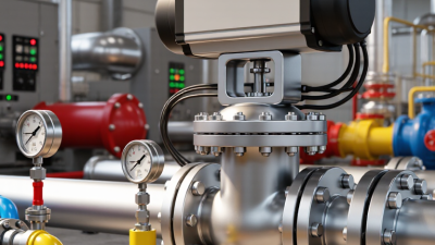
Mount the valve in the recommended flow direction, and leave enough space for wiring and service access. Flush the piping before connection. Small metal particles can damage the spool or create unstable movement. Use suitable seals, tighten fittings evenly, and protect electrical connections from moisture. During commissioning, increase the command signal gradually while checking pressure, temperature, and actuator movement. Do not assume the first setting is correct.

Tips:

Keep a written record of flow readings, signal values, and operating temperatures. Inspect filters and connectors during scheduled maintenance. Listen for buzzing, pulsing, or delayed actuator movement. These signs may indicate contamination, air, wiring faults, or incorrect calibration. Clean components only with approved fluids and tools. Avoid forcing a seized adjustment screw. In practice, maintenance intervals should reflect actual duty cycles, not only calendar dates. A valve working in dusty conditions may need earlier inspection. Even experienced technicians can overlook cable shielding or grounding, so verify both before replacing the valve.